Improve Your Quality With Glove Systems 3D Fabrication Control Platform
Complex 3D assemblies are hard to visualize and even harder to measure.
Glove Systems goes far beyond the limitations of today’s conventional measurement methods and represents the next generation of software-enabled fabrication quality control.
Our powerful Software as a Service platform provides quality assurance and quality control professionals with the coordinate measurement tools to visualize assemblies in 3D and perform highly detailed dimensional measurement of pipe spools and fabricated modules while allowing them to collaborate virtually with clients on design and delivery of fabrication projects.
With Glove Systems, fabricators can drive down costs, speed delivery and realize their “first time right goals” while achieving 20% improvements in process control and quality assurance.
Catch mistakes before they become costly
Increase your quality assurance/quality control capacity
Enable remote inspection and validation
Improve supply chain visibility
Reduce claims and litigation costs
The Glove Systems 3D Fabrication Control Platform

Enable rapid, accurate, and objective measurements while fabricating complex assemblies
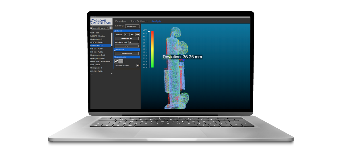
- Use state of the art 3D visualization for quick understanding of measurements and deviations.
- Highly repeatable and more accurate than traditional tape measurement methods.
- Store a digitally accurate digital twin and information in the Cloud for easy sharing and collaboration with clients.
- Information is securely available via the cloud, and can be accessed from any web-enabled browser.

- Creates a dimensionally-accurate 3D digital twin of as-built assemblies.
- Streamline the inspection and verification process by allowing clients to review, reject or accept as-built assemblies before they leave the shop.
- Heat map visually highlights deviations and can be adjusted to focus on different parts of the assembly.
- Have access to accurate Assembly Information Models
(AIM)
Compare received components against standard models.

- Compare received components against a library of 1,000s of 3D models of standard parts (flanges, tees, elbows and caps).
- Preserve quality by quickly rejecting non-conforming components.
- Mitigate project risk and minimize impacts on project schedules through rapid error detection.
- Share 3D copies of rejected parts and errors with suppliers to improve quality across the value chain.
Verify termination points are within tolerance


