Weld Distortion Calculation Using Glove Fit
“Don’t Get Bent Out Of Shape”
Problem
A Fabricator (the customer) is building a steel vessel that is used for containing liquids. These vessels are common in industry, and examples include rail car carriers for transporting liquids such as petroleum and chemicals. Made of steel, these vessels are fabricated for multiple industries and must be safe, secure, and strong.
To attach these cylindrical vessels to a flat surface securely, the fabricator affixes 18 steel mounts in two 3x3 grids to the vessel. These mounts are of different lengths due to the shape of the vessel; the ones closer to the periphery of the cylinder are longer than the ones near the center. These mounts must terminate evenly. Too much variance or too much offset, and the vessel will not be able to sit securely.
To attach these cylindrical vessels to a flat surface securely, the fabricator affixes 18 steel mounts in two 3x3 grids to the vessel. These mounts are of different lengths due to the shape of the vessel; the ones closer to the periphery of the cylinder are longer than the ones near the center. These mounts must terminate evenly. Too much variance or too much offset, and the vessel will not be able to sit securely.
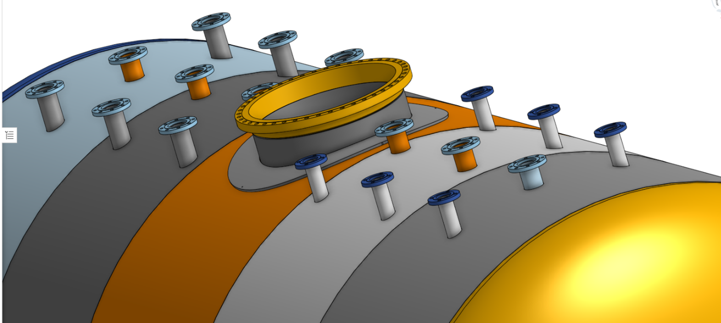
To complete the build, the fabricator cuts a large circular hole into the vessel, and a flange is then welded around the hole. The flange is used to connect the vessel to pipes such that it can be filled or drained. The flange is critical to the completion of the build. However, the flange presents specific challenges to the vessel build.
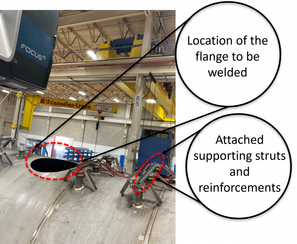
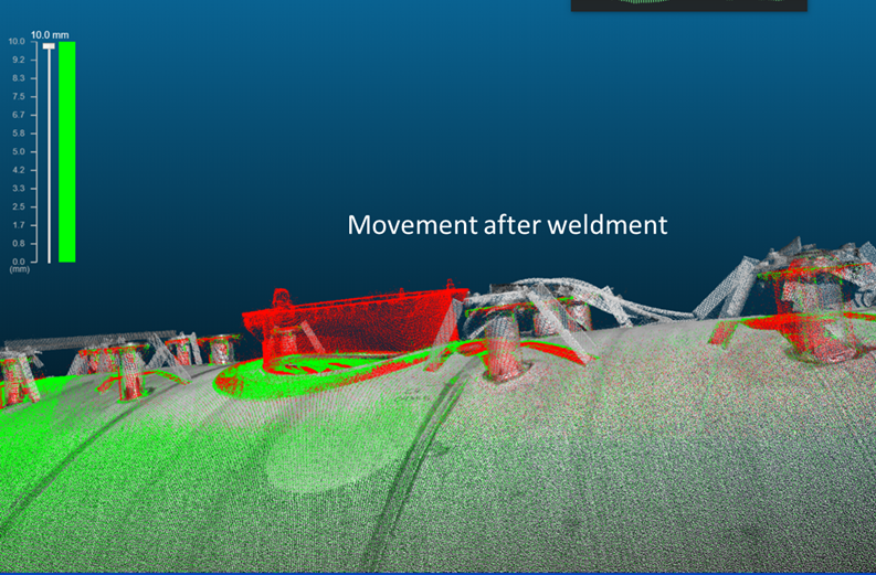
During the course of the flange’s weld, the heat causes small levels of distortion in the walls of the vessel. These distortions flex and bow the steel walls of the vessel and result in the mounts being offset from design. The range of the offset can be material, ranging from ¼”, and up to 1 1/16”, which is beyond acceptable margins of error. The shop welders attempt to mitigate this distortion effect by attaching supporting struts and reinforcements to the mounts. It is difficult for even the most experienced welders to predict the potential distortion which is influenced by the specific materials of the vessel and flange, vessel wall thickness, the size, weight and placement of the flange, and other environmental factors. Identifying distortion as quickly as possible can help reduce the amount of rework required to correct the vessel back to design.
During the course of the flange’s weld, the heat causes small levels of distortion in the walls of the vessel. These distortions flex and bow the steel walls of the vessel and result in the mounts being offset from design. The range of the offset can be material, ranging from ¼”, and up to 1 1/16”, which is beyond acceptable margins of error. The shop welders attempt to mitigate this distortion effect by attaching supporting struts and reinforcements to the mounts. It is difficult for even the most experienced welders to predict the potential distortion which is influenced by the specific materials of the vessel and flange, vessel wall thickness, the size, weight and placement of the flange, and other environmental factors. Identifying distortion as quickly as possible can help reduce the amount of rework required to correct the vessel back to design.
The Solution
The Fabricator used Glove Fit (Glove Software) to scan the existing tank, capture its design in digital format, and then compare this scan to a scan of the complete asset with the flange installed.
A FARO Focus scanner was used, which then generated an exact digital version of the tank (a technique called point cloud) into Glove Fit, an easy-to-use point-cloud measurement program by Glove. The point cloud is precise, complete, and highly accurate.
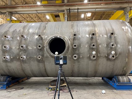
Welders continued to scan as they worked, comparing the incomplete vessel to the designs incrementally. This can be done quickly, without the need of traditional measurement tools (ruler, bubble level,) and by even junior welders.
Results
The table below shows the change in the mounts Pre and post weld, as revealed by Glove Fit:

